This post is to document the setup for a simple SPI Bus test using a RP2040 Nano Connect as a controller and the Arduino Uno as a peripheral device. The board connections look as follows:

I couldn’t find a good example of how to use the RPi4 as a peripheral device, and didn’t want to spend the time of coding it myself. So the Arduino Uno’s ATMega328p chip seemed like a reasonable fit for this — plenty of examples and simple enough for me to wrap my head around it.
With all that said I will be using the Arduino IDE to program both devices and the SPI library to handle byte transfers.
Useful Links
Peripheral Device Code
I like to start with the full picture and drill down into it, so below is the full code for the peripheral device.
/*
    SPI Bus Test
    Copyright (C) 2021  Travis Adsitt

    This program is free software: you can redistribute it and/or modify
    it under the terms of the GNU General Public License as published by
    the Free Software Foundation, either version 3 of the License, or
    (at your option) any later version.

    This program is distributed in the hope that it will be useful,
    but WITHOUT ANY WARRANTY; without even the implied warranty of
    MERCHANTABILITY or FITNESS FOR A PARTICULAR PURPOSE.  See the
    GNU General Public License for more details.

    You should have received a copy of the GNU General Public License
    along with this program.  If not, see <http://www.gnu.org/licenses/>.
*/

#include<SPI.h>

#define SPI_MODE 3
#define MAX_BUFFER_SIZE 50

volatile boolean received;
volatile byte peripheral_received,peripheral_send;

char print_buffer [50]; // Used for print formatting

byte *command_buffer;
byte *command_buffer_end;
byte *command_buffer_start;
int command_buffer_count;

byte *send_buffer;
byte *send_buffer_end;
byte *send_buffer_start;
int send_buffer_count;

int counter; // Counter to control
byte counter_low;
byte counter_high;

void setup()

{
  Serial.begin(115200);

  pinMode(MISO,OUTPUT);

  SPCR |= _BV(SPE);
  SPCR |= _BV(SPIE);
  // SPCR |= _BV(DORD);
  SPCR |= (SPI_MODE << 2);

  command_buffer_count = 0;

  command_buffer = calloc(0, MAX_BUFFER_SIZE);
  command_buffer_start = command_buffer;
  command_buffer_end = command_buffer;


  send_buffer_count = 0;

  send_buffer = calloc(0, MAX_BUFFER_SIZE);
  send_buffer_start = send_buffer;
  send_buffer_end = send_buffer;

  counter = 0;

  SPI.attachInterrupt();
}

void add_command_to_buffer(byte command){
  if(command_buffer_count == MAX_BUFFER_SIZE || command == 0x00) return;

  *command_buffer_end = command;

  if(command_buffer_end == (command_buffer + MAX_BUFFER_SIZE)){
    command_buffer_end = command_buffer;
  }else{
    command_buffer_end++;
  }

  command_buffer_count++;
}

byte get_command(){
  if(!command_buffer_count) return 0x00;

  byte command = *command_buffer_start;
  if(command_buffer_start == (command_buffer + MAX_BUFFER_SIZE)){
    command_buffer_start = command_buffer;
  }else{
    command_buffer_start++;
  }

  command_buffer_count--;

  return command;
}

byte get_send_buffer_byte(){
  if(!send_buffer_count) return 0x00;

  byte ret_send = *send_buffer_start;

  if(send_buffer_start == (send_buffer + MAX_BUFFER_SIZE)){
    send_buffer_start = send_buffer;
  }else{
    send_buffer_start++;
  }

  send_buffer_count--;

  return ret_send;
}

void add_byte_to_send_buffer(byte data_to_send){
  if(send_buffer_count == MAX_BUFFER_SIZE){
    return;
  }

  *send_buffer_end = data_to_send;

  if(send_buffer_end == (send_buffer + MAX_BUFFER_SIZE)){
    send_buffer_end = send_buffer;
  }else{
    send_buffer_end++;
  }

  send_buffer_count++;
}

ISR (SPI_STC_vect)
{
  byte command = SPDR;

  SPDR = get_send_buffer_byte();

  add_command_to_buffer(command);
}


void loop()
{
  if (command_buffer_count > 0) //Check for more commands
  {
    // Grab the next command to process
    peripheral_received = get_command();

    // Print command recieved
    sprintf(print_buffer,"Processing Command: %x Commands Left: %d",peripheral_received, command_buffer_count);
    Serial.println(print_buffer);
    switch(peripheral_received){
      case 0x01: // Add to the counter
        Serial.println("Adding to counter");
        counter++;
        break;
      case 0x02: // Get the counter
        add_byte_to_send_buffer(counter & 0xff);
        add_byte_to_send_buffer((counter >> 8) & 0xff);
        break;
      case 0x03: // Reset the counter
        Serial.println("Resetting the Counter");
        counter = 0;
        break;
      case 0x04: // Are you still there?
        Serial.println("Sending heartbeat");
        add_byte_to_send_buffer(0xff); // Yes :)
        break;
    }
    received = false;
  }
}
Ok to start lets look at the main loop…
void loop()
{
  if (command_buffer_count > 0) //Check for more commands
  {
    // Grab the next command to process
    peripheral_received = get_command();

    // Print command recieved
    sprintf(print_buffer,"Processing Command: %x Commands Left: %d",peripheral_received, command_buffer_count);
    Serial.println(print_buffer);
    switch(peripheral_received){
      case 0x01: // Add to the counter
        Serial.println("Adding to counter");
        counter++;
        break;
      case 0x02: // Get the counter
        Serial.println("Sending the Counter");
        add_byte_to_send_buffer(counter & 0xff);
        add_byte_to_send_buffer((counter >> 8) & 0xff);
        break;
      case 0x03: // Reset the counter
        Serial.println("Resetting the Counter");
        counter = 0;
        break;
      case 0x04: // Are you still there?
        Serial.println("Sending heartbeat");
        add_byte_to_send_buffer(0xff); // Yes :)
        break;
    }
    received = false;
  }
}
Our SPI bus is configured manually using the SPI Control Register(SPCR), I will leave it up to you to review the ATMega328P datasheet for more information on the bit values I set in there.
In the loop first we check to see if any new commands have come across the bus by checking the global variable ‘command_buffer_count’. If there are commands waiting then grab the next one in the queue with a call to ‘get_command()’. With the command stored in our ‘peripheral_received’ variable we can enter the switch case statement that identifies the commands we care about, namely:
- 0x01
- Add to our internal counter
- 0x02
- Send the current state of the counter
- 0x03
- Reset our counter
- 0x04
- Send heartbeat, this is used to verify there is indeed a device online
You might notice in each of the case blocks there are calls similar to our get_command() call to helper routines that manage a queue for us. Lets dig into this concept a bit.
A Queue for Command Management
Before we look at how the queue is setup and managed lets look at the Interrupt Service Routine(ISR) that is in our program:
ISR (SPI_STC_vect)
{
  byte command = SPDR;

  SPDR = get_send_buffer_byte();

  add_command_to_buffer(command);
}
This little block of code is run anytime there is a byte of data fully received and available in the SPI Data Register(SPDR), it is an interrupt because anything executing on the Microcontroller(MCU) at the time is immediately interrupted to handle the data in the buffer. You want your interrupt routines to be extremely simple as to not miss any data that might be being shifted in while you are executing the handler code.
So the first thing we do is grab the current byte from the register, and replace it with the next byte we want to send (if there isn’t a byte to send we replace it with 0x00). Then we add it to our command buffer queue to be processed in our main loop, we don’t process it here because that would be too compute expensive for the rate at which commands might be coming across the bus.
Finally we come to the concept of this queue… The command and send_data buffers are setup as such:
  command_buffer_count = 0;

  command_buffer = calloc(0, MAX_BUFFER_SIZE);
  command_buffer_start = command_buffer;
  command_buffer_end = command_buffer;


  send_buffer_count = 0;

  send_buffer = calloc(0, MAX_BUFFER_SIZE);
  send_buffer_start = send_buffer;
  send_buffer_end = send_buffer;
Basically we have an arbitrary ‘MAX_BUFFER_SIZE’ that we use with calloc(clear allocation, meaning we set all the memory to 0 in this case after we allocate it — this is more expensive but at least you know the start state of your memory) to get a set amount of memory for our buffer.
Then two pointers and a count variable to manage the queue are established, having all three of these can be seen as a bit of overkill considering you should be able to infer everything from a counter and list start pointer, or even start and end pointers to infer count, but I want to keep it simple and just track a bit more.
Using those buffers we have the command add and get routines below:
void add_command_to_buffer(byte command){
  if(command_buffer_count == MAX_BUFFER_SIZE || command == 0x00) return;

  *command_buffer_end = command;

  if(command_buffer_end == (command_buffer + MAX_BUFFER_SIZE)){
    command_buffer_end = command_buffer;
  }else{
    command_buffer_end++;
  }

  command_buffer_count++;
}

byte get_command(){
  if(!command_buffer_count) return 0x00;

  byte command = *command_buffer_start;
  if(command_buffer_start == (command_buffer + MAX_BUFFER_SIZE)){
    command_buffer_start = command_buffer;
  }else{
    command_buffer_start++;
  }

  command_buffer_count--;

  return command;
}
When adding a command we check if the buffer is full or the command is 0x00 and just return if either is the case. If not though, we set the end pointers data equal to the command handed in, check if we are at the end of the buffer and if so then wrap it to the buffers location if not we just add one to the buffer end pointer. Finally add one to the buffers count.
On the get command side we do much the same except we pull from the start of the buffer and set the start to +1 from its current location and subtract from the buffer_count.
For the send_data buffer you will see exactly the same layout:
byte get_send_buffer_byte(){
  if(!send_buffer_count) return 0x00;

  byte ret_send = *send_buffer_start;

  if(send_buffer_start == (send_buffer + MAX_BUFFER_SIZE)){
    send_buffer_start = send_buffer;
  }else{
    send_buffer_start++;
  }

  send_buffer_count--;

  return ret_send;
}

void add_byte_to_send_buffer(byte data_to_send){
  if(send_buffer_count == MAX_BUFFER_SIZE){
    return;
  }

  *send_buffer_end = data_to_send;

  if(send_buffer_end == (send_buffer + MAX_BUFFER_SIZE)){
    send_buffer_end = send_buffer;
  }else{
    send_buffer_end++;
  }

  send_buffer_count++;
}
In fact, it is so similar it might make sense to generalize the functions and let the caller specify the buffer using a struct or something… For now that is all for the peripheral device.
Controller Device Code
If you are still with me the controller code is much simpler and should be a breeze to review. Again we will start with the whole picture:
/*
    SPI Bus Test
    Copyright (C) 2021  Travis Adsitt

    This program is free software: you can redistribute it and/or modify
    it under the terms of the GNU General Public License as published by
    the Free Software Foundation, either version 3 of the License, or
    (at your option) any later version.

    This program is distributed in the hope that it will be useful,
    but WITHOUT ANY WARRANTY; without even the implied warranty of
    MERCHANTABILITY or FITNESS FOR A PARTICULAR PURPOSE.  See the
    GNU General Public License for more details.

    You should have received a copy of the GNU General Public License
    along with this program.  If not, see <http://www.gnu.org/licenses/>.
*/

#include<SPI.h>

// Define our Chip Select pin
#define CS 10

// SPI settings
SPISettings settings(9600, LSBFIRST, SPI_MODE3);

char print_buffer [50]; // Used for print formatting

void setup()
{
  // Begin a serial session for debug printing
  Serial.begin(9600);
  // Begin our SPI bus library functionality
  SPI.begin();

  // Setup all pin podes
  pinMode(CS, OUTPUT);
  pinMode(MOSI, OUTPUT);
  pinMode(MISO, INPUT);
  pinMode(SCK, OUTPUT);
  pinMode(9, OUTPUT);

  // Set our Chip Select high, this turns it 'off'
  digitalWrite(CS, HIGH);
}

void loop(void)
{
  // A place for us to store the counter when we request it
  int counter = 0;

  // Drop Chip Select and begin a transaction
  digitalWrite(CS, LOW);
  SPI.beginTransaction(settings);

  // We are simply going to count up and send as a command
  int i = 1;
  while(i < 5){
    // If we are sending a two expect the return to
    // be the current counters value.
    if(i == 2){
      counter = SPI.transfer(i);
    }else{
      SPI.transfer(i);
    }
    i++;
  }
  // Send 0x00 to clear SPDR preventing bad data on next transaction
  SPI.transfer(0x00);
  // Bring chip select back up and end the transaction
  digitalWrite(CS, HIGH);
  SPI.endTransaction();

  // Print our counter and delay for easier reading on serial
  // terminal.
  sprintf(print_buffer,"Counter Lower Value: %x",counter);
  Serial.println(print_buffer);
  delay(500);
}
The setup section is just specifying the pin modes for the SPI library and ourselves. We control the Chip Select(CS) line but the rest is handled by the SPI library. Despite the library handling things I highly recommend reading up on what that library is doing, it is really impressive and very cool.
Anyway, in the main loop you will see we are simply counting from 0-4 and sending the current index as a command to the peripheral. We capture the return value when sending 2 as that should return the value of the counter. And because we are in Least Significant Bit First(LSBFIRST) mode we expect the first bit to be a one as we have only added 1 to the peripherals counter. If we cared to look, when we send the 4 we would expect also to see the 0xFF of the heartbeat, that can be seen in the O-Scope capture below:
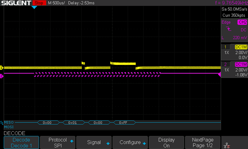
In this picture you can actually see the decoded values below the wave form, this includes the heartbeat at the end.
Output
Peripheral Serial Output
Processing Command: 1 Commands Left: 0
Adding to counter
Processing Command: 2 Commands Left: 0
Sending the Counter
Processing Command: 3 Commands Left: 1
Resetting the Counter
Processing Command: 4 Commands Left: 0
Sending heartbeat
Here we see the command that is being processed along with the queue remaining. Because it is such a short burst we see it only start to stack commands when we are processing command ‘0x03’.
Controller Serial Output
Counter Lower Value: 1As expected we receive a value of one from the peripheral.
Conclusion
This dive into SPI communication was very informative for me, I hope this article is helpful in guiding someone else by showing a working example. Please comment if you find any inaccuracies that should be corrected or would like to discuss the content. Thank you for reading!